
Panamax M4315-PRO Controller
Panamax M4315-PRO Controller
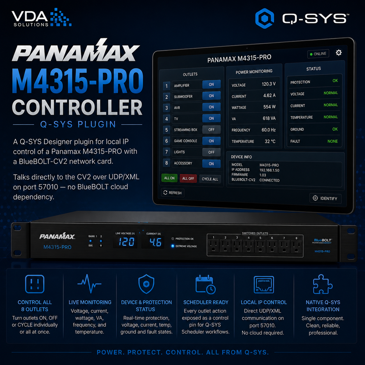
A Q-SYS Designer plugin for local IP control of a Panamax M4315-PRO with a BlueBOLT-CV2 network card. Talks directly to the CV2 over UDP/XML on port 57010 — no BlueBOLT cloud dependency.
Controls all 8 BlueBOLT-switchable outlets (on / off / cycle), exposes live monitoring (voltage, current, wattage, VA, temperature, fault states), and surfaces every outlet action as a control pin so you can drive reboots from a Q-SYS Scheduler component.
Installation
Download Panamax_M4315.qplugx
Drop it into your Q-SYS Designer plugins folder:
Mac: ~/Documents/QSC/Q-Sys Designer/Plugins/
Windows: Documents\QSC\Q-Sys Designer\Plugins\
Restart Q-SYS Designer
The plugin appears under User → Panamax → M4315-PRO Controller in the plugin list — drag it into your design
Setup
Add the plugin to your design
In the Connection panel, enter:
IP Address — the BlueBOLT-CV2's local IP (find it on the CV2 admin page or in BlueBOLT cloud)
MAC (last 6) — the last 6 hex digits of the CV2's MAC address (printed on the label of the CV2 card and its packaging)
Press Connect
Status turns green when the plugin receives the first status response. Monitoring fields and outlet state LEDs populate automatically.
Poll interval defaults to 30 seconds and is adjustable (5–300). Press Refresh for an immediate query.
Outlet control
Each of the 8 outlets has:
State LED — on/off indicator from the unit
Label field — name the outlet (e.g. "DTV Boxes", "Rack Switch")
On / Off / Cycle buttons — immediate commands
Toggle — on/off in a single button with state feedback
Group actions: All On, All Off, All Cycle, and Run Sequence (runs the unit's built-in sequenced turn-on/turn-off using its configured per-outlet delays).
Scheduling with the Q-SYS Scheduler component
The plugin doesn't have its own scheduler — every outlet action is exposed as a control pin, so you drive schedules from Q-SYS's built-in Scheduler component.
Example — reboot everything on the Panamax every day at 06:00:
Drop a Scheduler component into your design
Add a daily event at 06:00:00
Wire the event's trigger output to the plugin's All Cycle pin
For per-outlet schedules:
Wire the scheduled event to the specific Outlet N Cycle, Outlet N On, or Outlet N Off pin
The Scheduler supports daily, weekly, and one-off events, which covers everything without any plugin-side persistence
Monitoring
All monitoring values are both displayed in the plugin UI and exposed as output pins, so you can log them, threshold-alert on them, or show them on a UCI:
Voltage (Vac), Current (A), Wattage (W), VA
Temperature (°C)
Voltage Fault, Wiring Fault, Breaker Fault (LED outputs)
Trigger In (LED — reflects the DC trigger input on the back of the unit)
Building a UCI
The plugin exposes every control in the component's control list. To build a UCI, open the plugin and drag controls straight from the plugin onto your UCI page — each drop keeps its connection to the plugin automatically. Style buttons, LEDs, and text fields in the UCI editor (size, colors, fill, stroke) like any other UCI element.
The layering technique works well here too: drop a rack graphic as the background, overlay Outlet N Cycle buttons on each outlet position, add Outlet N State LEDs styled transparent-off / green-on to visualize live state.
Key Controls / Pins
PinDirectionPurposeIPInputCV2 IP addressMAC Last 6InputLast 6 hex digits of CV2 MACConnectedOutputLED — receiving responses from the unitOutlet Name 1..8InputUser-editable outlet labelsOutlet State 1..8OutputLive on/off per outletOutlet On 1..8InputTurn an outlet onOutlet Off 1..8InputTurn an outlet offOutlet Cycle 1..8InputPower cycle an outletOutlet Toggle 1..8Input/OutputToggle + stateAll On, All Off, All CycleInputGroup actions on all 8 outletsRun SequenceInputRun the unit's built-in sequenced power cycleVoltage, Current, Wattage, VA, TemperatureOutputLive metersVoltage Fault, Wiring Fault, Breaker Fault, Trigger InOutputStatus LEDs
Notes
Local control uses UDP port 57010 — the Q-SYS core and the CV2 must be on the same network, and the CV2 web interface cannot block the UDP port (it doesn't).
Password protection on the CV2's embedded web interface does not affect this plugin — UDP commands are not authenticated by the device.
The M4315-PRO physically has 9 outlets, but only 8 are under BlueBOLT control. The 9th is the always-on "power lock" bank and isn't exposed in the protocol.
Outlet sequence delays (turn-on / turn-off / cycle) are configured on the unit itself (embedded web page or BlueBOLT cloud) and are applied during Run Sequence and individual cycles.
Panamax M4315-PRO Controller
A Q-SYS Designer plugin for local IP control of a Panamax M4315-PRO with a BlueBOLT-CV2 network card. Talks directly to the CV2 over UDP/XML on port 57010 — no BlueBOLT cloud dependency.
Controls all 8 BlueBOLT-switchable outlets (on / off / cycle), exposes live monitoring (voltage, current, wattage, VA, temperature, fault states), and surfaces every outlet action as a control pin so you can drive reboots from a Q-SYS Scheduler component.
Installation
Download Panamax_M4315.qplugx
Drop it into your Q-SYS Designer plugins folder:
Mac: ~/Documents/QSC/Q-Sys Designer/Plugins/
Windows: Documents\QSC\Q-Sys Designer\Plugins\
Restart Q-SYS Designer
The plugin appears under User → Panamax → M4315-PRO Controller in the plugin list — drag it into your design
Setup
Add the plugin to your design
In the Connection panel, enter:
IP Address — the BlueBOLT-CV2's local IP (find it on the CV2 admin page or in BlueBOLT cloud)
MAC (last 6) — the last 6 hex digits of the CV2's MAC address (printed on the label of the CV2 card and its packaging)
Press Connect
Status turns green when the plugin receives the first status response. Monitoring fields and outlet state LEDs populate automatically.
Poll interval defaults to 30 seconds and is adjustable (5–300). Press Refresh for an immediate query.
Outlet control
Each of the 8 outlets has:
State LED — on/off indicator from the unit
Label field — name the outlet (e.g. "DTV Boxes", "Rack Switch")
On / Off / Cycle buttons — immediate commands
Toggle — on/off in a single button with state feedback
Group actions: All On, All Off, All Cycle, and Run Sequence (runs the unit's built-in sequenced turn-on/turn-off using its configured per-outlet delays).
Scheduling with the Q-SYS Scheduler component
The plugin doesn't have its own scheduler — every outlet action is exposed as a control pin, so you drive schedules from Q-SYS's built-in Scheduler component.
Example — reboot everything on the Panamax every day at 06:00:
Drop a Scheduler component into your design
Add a daily event at 06:00:00
Wire the event's trigger output to the plugin's All Cycle pin
For per-outlet schedules:
Wire the scheduled event to the specific Outlet N Cycle, Outlet N On, or Outlet N Off pin
The Scheduler supports daily, weekly, and one-off events, which covers everything without any plugin-side persistence
Monitoring
All monitoring values are both displayed in the plugin UI and exposed as output pins, so you can log them, threshold-alert on them, or show them on a UCI:
Voltage (Vac), Current (A), Wattage (W), VA
Temperature (°C)
Voltage Fault, Wiring Fault, Breaker Fault (LED outputs)
Trigger In (LED — reflects the DC trigger input on the back of the unit)
Building a UCI
The plugin exposes every control in the component's control list. To build a UCI, open the plugin and drag controls straight from the plugin onto your UCI page — each drop keeps its connection to the plugin automatically. Style buttons, LEDs, and text fields in the UCI editor (size, colors, fill, stroke) like any other UCI element.
The layering technique works well here too: drop a rack graphic as the background, overlay Outlet N Cycle buttons on each outlet position, add Outlet N State LEDs styled transparent-off / green-on to visualize live state.
Key Controls / Pins
PinDirectionPurposeIPInputCV2 IP addressMAC Last 6InputLast 6 hex digits of CV2 MACConnectedOutputLED — receiving responses from the unitOutlet Name 1..8InputUser-editable outlet labelsOutlet State 1..8OutputLive on/off per outletOutlet On 1..8InputTurn an outlet onOutlet Off 1..8InputTurn an outlet offOutlet Cycle 1..8InputPower cycle an outletOutlet Toggle 1..8Input/OutputToggle + stateAll On, All Off, All CycleInputGroup actions on all 8 outletsRun SequenceInputRun the unit's built-in sequenced power cycleVoltage, Current, Wattage, VA, TemperatureOutputLive metersVoltage Fault, Wiring Fault, Breaker Fault, Trigger InOutputStatus LEDs
Notes
Local control uses UDP port 57010 — the Q-SYS core and the CV2 must be on the same network, and the CV2 web interface cannot block the UDP port (it doesn't).
Password protection on the CV2's embedded web interface does not affect this plugin — UDP commands are not authenticated by the device.
The M4315-PRO physically has 9 outlets, but only 8 are under BlueBOLT control. The 9th is the always-on "power lock" bank and isn't exposed in the protocol.
Outlet sequence delays (turn-on / turn-off / cycle) are configured on the unit itself (embedded web page or BlueBOLT cloud) and are applied during Run Sequence and individual cycles.